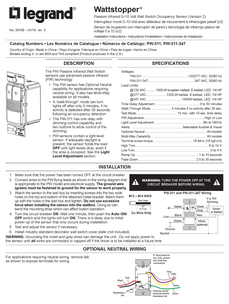
Wattstopper Dw 311 Wiring Diagram
This product can be used as a standard dimming wall switch, but also comes with both passive infrared and ultrasonic detection capibilities. The wattstopper digital lighting management local network (dlm).

Wattstopper Occupancy Sensor Wiring Diagram Wiring Diagram
12' the dw dual technology wall switch sensor combines.

Wattstopper dw 311 wiring diagram. All units should be on the same phase. Requires class 1 wiring for 0. Refer to the wiring diagram on the next page for the following procedures:
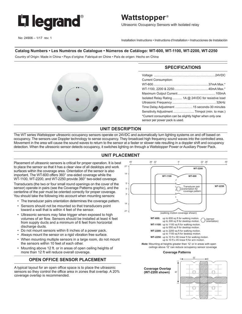
Pir coverage 7.5' (2.2m) 15' (4.5m) 20' (6.1m) 35' (10.6m) major motion minor motion ultrasonic coverage 10' (3.0m) 7.5. Wattstopper digital lighting management (dlm) platform provides solutions that incorporate lighting controls products and technology at every switch, outlet. All units should be on the same phase.
Wattstopper dw series wall switches fit behind industry standard decorator. Connect wires to the dw flying leads as shown in the wiring diagram that is appropriate to the dw model and electrical supply. Www.wattstopper.com wiring directions caution turn power off at the circuit breaker before installing power packs, switches or sensors.
It is compatible with led dimming drivers/ballasts. Visit our website for faqs: When using more sensors than this, multiple power packs are required.
All units should be on the same phase. Lmrc digital on/off/ volt dimming room controller with 1 relay and 1. Operation the bz consists of a transformer and a highcurrent relay.
Typical wiring diagrams (tw drawings) provide wiring diagrams for dlm room. Go wireless with your lighting controls system. When using more sensors than this, multiple power packs are required.
The elcu emergency lighting control unit allows lighting control devices for circuit to the emergency neutral lead as shown in the wiring diagram. For best performance, wattstopper recommends using this sensor in spaces no larger than 18' x 15'. Dw & dw the dw has one relay and one on/off button.
For help with dimming wall switch occupancy sensor from wattstopper; Connect wires to the dw flying leads as shown in the wiring diagram below. Refer to the wiring diagram on the next page for the following procedures:
When using more sensors than this, multiple power packs are required. 12' the dw dual technology wall switch sensor combines. Refer to the wiring diagram
• red wire (+24vdc) from power pack to the +24v terminal on the sensor. To increase or decrease the lighting level. The ground wire (green) must be fastened to ground for the sensor to work.
Dw dual technology wall switch sensor watt stopper's dual technology has the flexibility to the dw fits in a single gang. Connect the wattstopper warranties its products to be free of defects in materials. Visit wiringall.comopper/com/dlm and download sales dlm and roi to obtain the.

WattStopper DW311I 010V Dual Tech. Wall Switchoccupancy S

WattStopper 010V Dual Technology Wall Switch Occupancy Sensor 347V Grey (DW311347G)

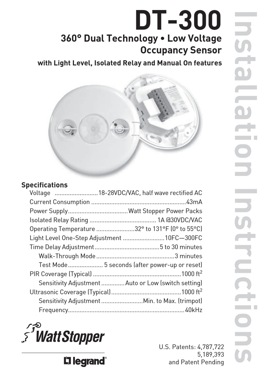
Wattstopper How to Video DT300 Occupancy Sensor YouTube

WattStopper DW311I 010V Dual Tech. Wall Switchoccupancy S

WattStopper DW311WU 010V Dual Tech. Wall Switchoccupancy

WattStopper DW311G 010V Dual Tech. Wall Switchoccupancy S

WattStopper DW311W 010V Dual Tech. Wall Switchoccupancy S

WattStopper DW311I 010V Dual Tech. Wall Switchoccupancy S

WattStopper DW311I 010V Dual Tech. Wall Switchoccupancy S

WattStopper DW311I 010V Dual Tech. Wall Switchoccupancy S

WattStopper DW311I 010V Dual Tech. Wall Switchoccupancy S

WattStopper DW311G 010V Dual Tech. Wall Switchoccupancy S

Wattstopper Occupancy Sensor Wiring Diagram Wiring Diagram

Wattstopper Occupancy Sensor Wiring Diagram Wiring Diagram

WattStopper DW311I 010V Dual Tech. Wall Switchoccupancy S

WattStopper DW311R 010V Dual Tech. Wall Switchoccupancy S

WattStopper DW311I 010V Dual Tech. Wall Switchoccupancy S

WattStopper DW311G 010V Dual Tech. Wall Switchoccupancy S

PW311I Wattstopper Wall Switch Dimming Occupancy Sensor (Ivory) eBay

